Replace your Chitu Firmware with Marlin on your Tronxy 3D Printer
After a couple of years with my improved and tuned Anet A6 it was time for a bigger machine, and I decided to buy a Tronxy X5SA-2E, as I wanted a dual extruder setup. The assembly was straight-forward but the printing… I was used to Marlin and the Chitu Firmware is just a pain with their proprietary limitations and weird custom GCodes. So the obvious step was to replace the firmware with Marlin. Before I bought the printer I read up about the improvements the community was doing on bringing Marlin on Tronxy devices, this was actually a factor before buying the printer.
This guide is more a documentation for me and a translation of r3xx0n’s work here.
You will find a lot of config changes and you should understand every single one of them. I will update my Marlin Fork on Github with my current firmware.
UPDATE: You can find some special parts like the BL-Touch mount in git too.
Backup everything
Print necessary parts
If you don’t own a second printer, you might want to print the mount for the BL-Touch sensor beforehand: You can find the mount in my git project
Config Backup
Let’s start with backing up the current config by creating a file named savesettings.gcode and save it on an empty fat32 formatted micro sd-card.
M6046 ; sdcard access
M8512 "currentconfig.gcode" ; save settings to file
Put the sd-card into your printer and “print” it. Wait for 15 to 30 seconds, abort the print, power off the printer and remove the sd-card. You should now find another file on the card named currentconfig.gcode.
Firmware Backup
Shutdown the printer, remove the power cable and remove every cable from the controller. Remove the controller from the frame and open the case of the controller.
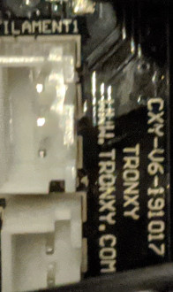
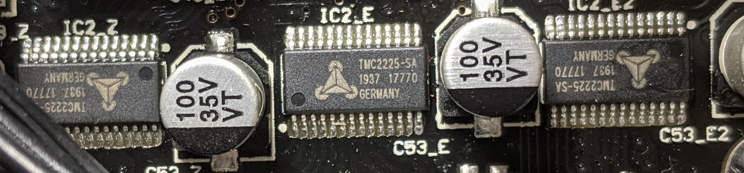
Write down the Board Version e.g. CXY-V6-191017 and write down the stepper driver model, as we need this info later for the Marlin Configuration.
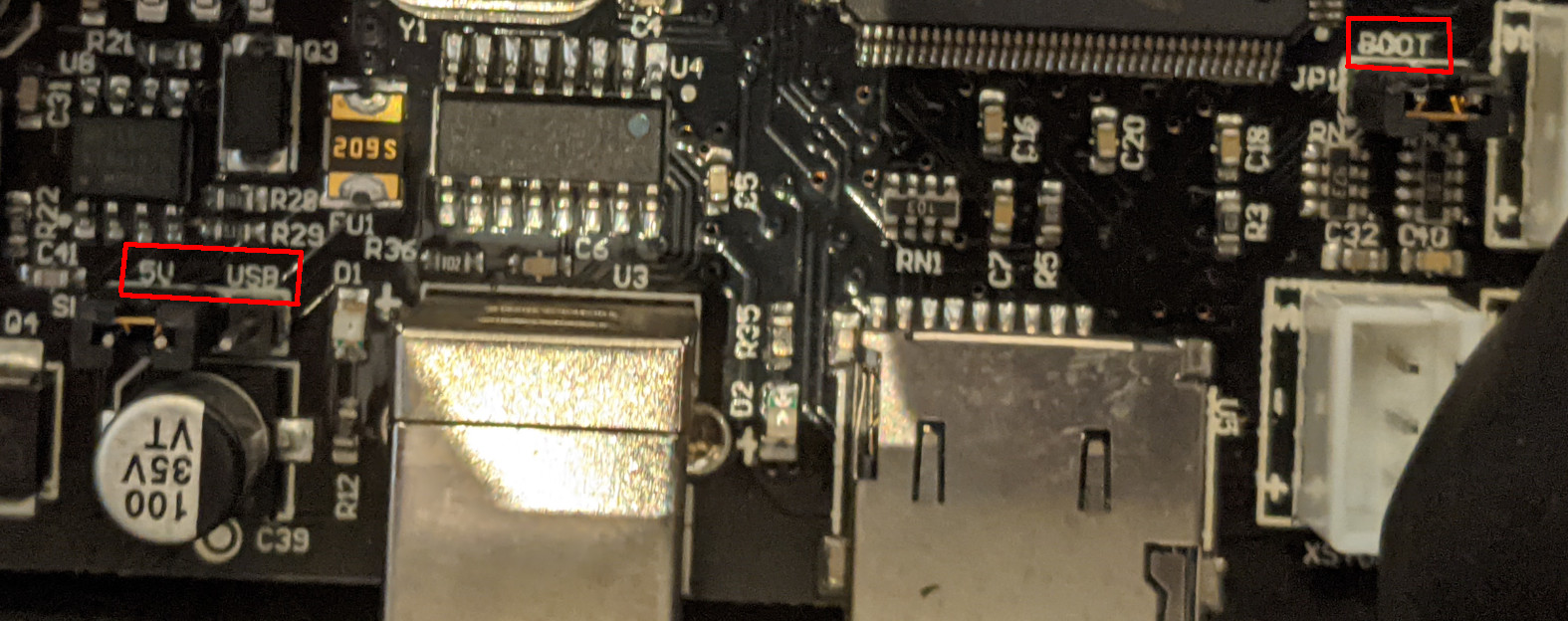
Now one need to find two jumpers 5V and Boot. 5V needs to be set to USB (while 5V is default) and the Boot jumper needs to be removed.
Now download STM Cube Programmer which runs on MacOS, Windows and Linux. You can obviously choose any other software which reads the flash, this one was easy to set up and worked out of the box.
Connect the controller to your computer via USB, no need to connect the power supply! USB is enough.
Select your serial port and click on Connect.
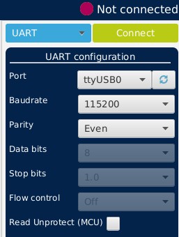
You will now find some information about the chip, for example the flash size, which holds the firmware.
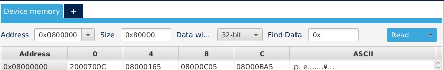
So next step is to download the firmware from the flash. The address is 0x0800000 by default and the only option. Now enter 0x80000 as size, which equals 524288 Bytes or 512 kB. So we are cloning the flash bitwise. You can now click on Read and choose Save As.. in the pull-down menu of the Read button, after the flash was successfully read.
This can take a while. Save the file and double check if the file has a size of 512kB or 524288 Bytes.
After you saved the file, you can load the file again into the program and double check if the values match the flash.
Click on Disconnect in the program and disconnect the USB cable from your computer and the controller board.
Reset the jumpers to their original positions (Boot jumper is set, and power source is set to 5V instead of USB) and reassemble the board.
It’s time for Marlin
Clone the repo
Instead of using a stale fork, we are cloning the current 2.0.x branch straight from the main git project. But I still decided to look into the Configuration.h of rhapsodyv to get a basis of my settings. All these settings can be tuned later on.
git clone https://github.com/MarlinFirmware/Marlin.gitCheck out the tagof the latest release, I used 2.0.7.2
cd Marlin
git checkout 2.0.7.2
Adapt the configuration
Edit the Configuration.h file for the proper setup. Look at your board version and check with the boards.h file to find your board.
In my case it is BOARD_CHITU3D_V6.
Make sure that you have at least the following config set as here described, otherwise there is the risk that either endstops, filament sensors, extruders, movement or the controller fan is not working.
#ifndef MOTHERBOARD
  #define MOTHERBOARD BOARD_CHITU3D_V6
#endif
Baudrate is normally 115200
#define BAUDRATE 115200In my case it’s a dual extruder version X5SA-2E:
// This defines the number of extruders
// :[0, 1, 2, 3, 4, 5, 6, 7, 8]
#define EXTRUDERS 2
...
// For Cyclops or any "multi-extruder" that shares a single nozzle.
#define SINGLENOZZLE
Enable COREXY - CoreXY uses a special belt arrangement to do XY motion, requiring a little extra maths.
// Enable one of the options below for CoreXY, CoreXZ, or CoreYZ kinematics,
// either in the usual order or reversed
#define COREXY
Disable Pullup for Endstops
// Enable pullup for all endstops to prevent a floating state
//#define ENDSTOPPULLUPS
Invert the end-stops:
// Mechanical endstop with COM to ground and NC to Signal uses "false" here (most common setup).
#define X_MIN_ENDSTOP_INVERTING true // Set to true to invert the logic of the endstop.
#define Y_MIN_ENDSTOP_INVERTING true // Set to true to invert the logic of the endstop.
#define Z_MIN_ENDSTOP_INVERTING true // Set to true to invert the logic of the endstop.
#define X_MAX_ENDSTOP_INVERTING false // Set to true to invert the logic of the endstop.
#define Y_MAX_ENDSTOP_INVERTING false // Set to true to invert the logic of the endstop.
#define Z_MAX_ENDSTOP_INVERTING false // Set to true to invert the logic of the endstop.
#define Z_MIN_PROBE_ENDSTOP_INVERTING true // Set to true to invert the logic of the probe.
Configure Stepper Driver to TMC2208_STANDALONE if you have a TMC2225-SA Chip
#define X_DRIVER_TYPE  TMC2208_STANDALONE
#define Y_DRIVER_TYPE  TMC2208_STANDALONE
#define Z_DRIVER_TYPE  TMC2208_STANDALONE
//#define X2_DRIVER_TYPE A4988
//#define Y2_DRIVER_TYPE A4988
//#define Z2_DRIVER_TYPE A4988
//#define Z3_DRIVER_TYPE A4988
//#define Z4_DRIVER_TYPE A4988
#define E0_DRIVER_TYPE TMC2208_STANDALONE
#define E1_DRIVER_TYPE TMC2208_STANDALONE
//#define E2_DRIVER_TYPE A4988
//#define E3_DRIVER_TYPE A4988
//#define E4_DRIVER_TYPE A4988
//#define E5_DRIVER_TYPE A4988
//#define E6_DRIVER_TYPE A4988
//#define E7_DRIVER_TYPE A4988
Steps per Unit need to be calculated from the savedsettings.conf file.
Find the lines
M8009 S0.006250;x,y
M8010 S0.001250;z
M8011 S0.001308;e
The calculation is a simple 1/$value like 1/0.00625 -> = 160
#define DEFAULT_AXIS_STEPS_PER_UNIT { 160, 160, 800, 764 }Set the acceleration:
#define DEFAULT_MAX_ACCELERATION      { 1500, 1500, 100, 5000 }
...
#define DEFAULT_ACCELERATION          1500    // X, Y, Z and E acceleration for printing moves
#define DEFAULT_RETRACT_ACCELERATION  1500    // E acceleration for retracts
#define DEFAULT_TRAVEL_ACCELERATION   1500    // X, Y, Z acceleration for travel (non printing) moves
Configure the level sensor as Z-Endstop and use it for homing
/**
 * Enable this option for a probe connected to the Z-MIN pin.
 * The probe replaces the Z-MIN endstop and is used for Z homing.
 * (Automatically enables USE_PROBE_FOR_Z_HOMING.)
 */
#define Z_MIN_PROBE_USES_Z_MIN_ENDSTOP_PIN

// Force the use of the probe for Z-axis homing
#define USE_PROBE_FOR_Z_HOMING

#define FIX_MOUNTED_PROBE

#define NOZZLE_TO_PROBE_OFFSET { -30, -5, 0 }

#define PROBING_HEATERS_OFF
And some more config…
Configure machine limits
// Invert the stepper direction. Change (or reverse the motor connector) if an axis goes the wrong way.
#define INVERT_X_DIR true
#define INVERT_Y_DIR true
#define INVERT_Z_DIR false

// @section extruder

// For direct drive extruder v9 set to true, for geared extruder set to false.
#define INVERT_E0_DIR true
#define INVERT_E1_DIR true
#define INVERT_E2_DIR false
#define INVERT_E3_DIR false
#define INVERT_E4_DIR false
#define INVERT_E5_DIR false
#define INVERT_E6_DIR false
#define INVERT_E7_DIR false

#define Z_HOMING_HEIGHT  10      // (mm) Minimal Z height before homing (G28) for Z clearance above the bed, clamps, ...
                                  // Be sure to have this much clearance over your Z_MAX_POS to prevent grinding.

#define Z_AFTER_HOMING  10      // (mm) Height to move to after homing Z

// The size of the print bed
#define X_BED_SIZE 330
#define Y_BED_SIZE 330

// Travel limits (mm) after homing, corresponding to endstop positions.
#define X_MIN_POS 0
#define Y_MIN_POS 0
#define Z_MIN_POS 0
#define X_MAX_POS X_BED_SIZE
#define Y_MAX_POS Y_BED_SIZE
#define Z_MAX_POS 400
Configure the Filament runout sensors:
#define FILAMENT_RUNOUT_SENSOR
#if ENABLED(FILAMENT_RUNOUT_SENSOR)
//#define FIL_RUNOUT_ENABLED_DEFAULT true // Enable the sensor on startup. Override with M412 followed by M500.
#define NUM_RUNOUT_SENSORS 2  // Number of sensors, up to one per extruder. Define a FIL_RUNOUT#_PIN for each.
#define FIL_RUNOUT_STATE HIGH // Pin state indicating that filament is NOT present.
//#define FIL_RUNOUT_PULLUP               // Use internal pullup for filament runout pins.
//#define FIL_RUNOUT_PULLDOWN           // Use internal pulldown for filament runout pins.

// Set one or more commands to execute on filament runout.
// (After 'M412 H' Marlin will ask the host to handle the process.)
#define FILAMENT_RUNOUT_SCRIPT "M600"

// After a runout is detected, continue printing this length of filament
// before executing the runout script. Useful for a sensor at the end of
// a feed tube. Requires 4 bytes SRAM per sensor, plus 4 bytes overhead.
//#define FILAMENT_RUNOUT_DISTANCE_MM 25

#ifdef FILAMENT_RUNOUT_DISTANCE_MM
// Enable this option to use an encoder disc that toggles the runout pin
// as the filament moves. (Be sure to set FILAMENT_RUNOUT_DISTANCE_MM
// large enough to avoid false positives.)
//#define FILAMENT_MOTION_SENSOR
#endif
#endif
Set up ABL, LCD and more.
#define AUTO_BED_LEVELING_LINEAR

#define Z_SAFE_HOMING

#define EEPROM_SETTINGS

#define SPEAKER

#define TFT_TRONXY_X5SA

#define TFT_COLOR_UI
Advanced Configuration
Now we need to dig a bit deeper and set some settings in to Configuration_adv.h
#define USE_CONTROLLER_FAN

#define E0_AUTO_FAN_PIN FAN_PIN_2
#define E1_AUTO_FAN_PIN FAN_PIN_2
add dwc_otg.speed=1to /boot/cmdline.txt on your RPI3 to make sure the serial interface is showing up.
It should look like this afterwards:
console=serial0,115200 console=tty1 ... rootwait *dwc_otg.speed=1*Compile and flash
Easiest is to use platformio with vscode to.
The platformio.ini should have this config in the beginning
[platformio]
src_dir      = Marlin
boards_dir   = buildroot/share/PlatformIO/boards
default_envs = chitu_f103
include_dir  = Marlin
After you adapted your config, you can try to compile Marlin. If everything worked, you should fine some files in the .pio/build/chitu_f103 folder.
The terminal in vscode should show you, if marlin was compiled successfully.
Environment    Status    Duration
-------------  --------  ------------
chitu_f103     SUCCESS   00:01:46.381
Copy the .pio/build/chitu_f103/update.cbd on the root of an empty FAT32 formatted SD Card.
Turn off the printer, insert the card and turn the printer back on. The firmware is installed automatically.
Test everything
- test all endstops before you do anything else by checking the status with a GCODE (
M119) and pressing the endstops manually - heat up Hotend and Bed
- run a thermal PID on Hotend and Bed
- test the extruder(s)
- test movement
- test homing
- test printing
Replace PL-08N inductive promixity sensor with BL-Touch
Because all this wasn’t already hard enough, we will replace the less precise PL-08N with a more precise BL-Touch or one of it’s clones.
So look at the following Pin-Out:
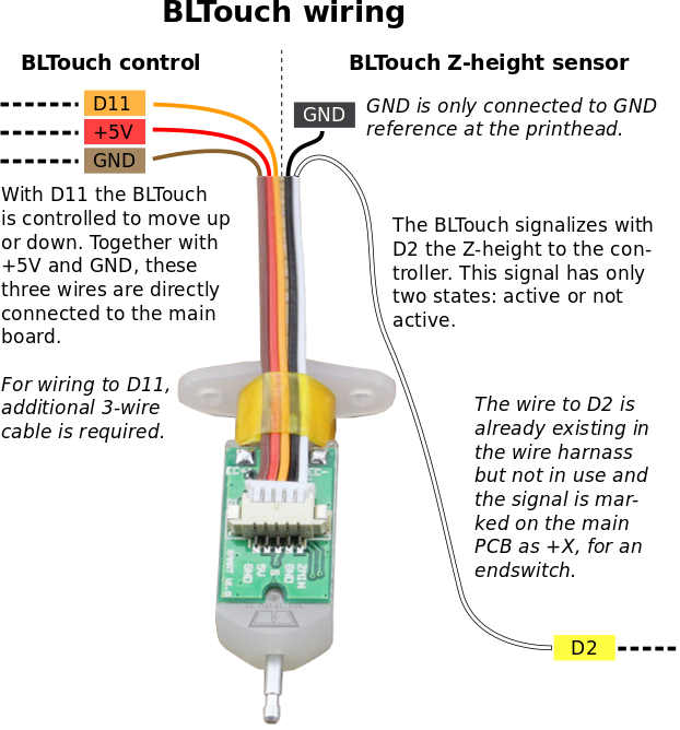
D11 is used as a servo pin. While D2 is actually our endstop / level signal.
You can not plug in the BL-Touch into the port of the proximity sensor as it runs with 24V! You will fry your BL-Touch. Use a multimeter to be safe! We will only use signal and grab ground, 5V and servo from somewhere else.
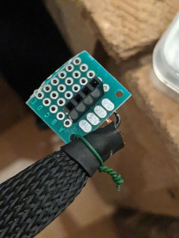
As there are not free Pins on the extension board so I went looking for an alternative.
Here comes Zubus from thingiverse with his idea to use the wifi pins.
But I wasn’t happy using one cable from the wifi port and adding Y-Cables for 5V and GND from a filament sensor.
Let’s look at the Pin out!
Thanks to snovotill from the RepRap Forum for the reverse engineering of the PCB Pins.
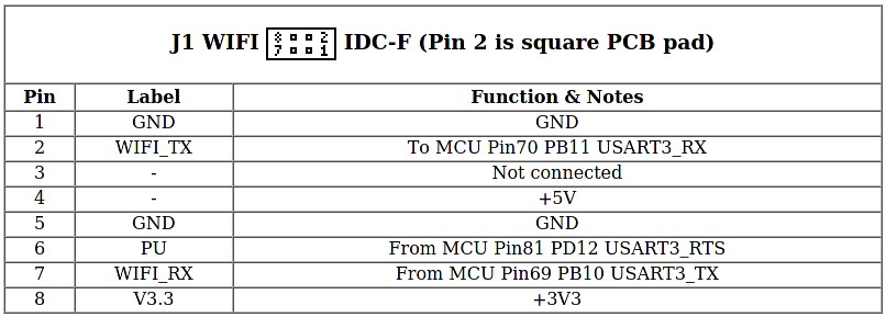
So let’s use Pin4 for 5V, Pin6 for servo and Pin1 or Pin5 for GND. I decided to use Pin1.
So I decided to do a proper connector on both ends. I crimped another cable for the chain to connect to these Dupont Pins on the BL Touch end and on my connector.
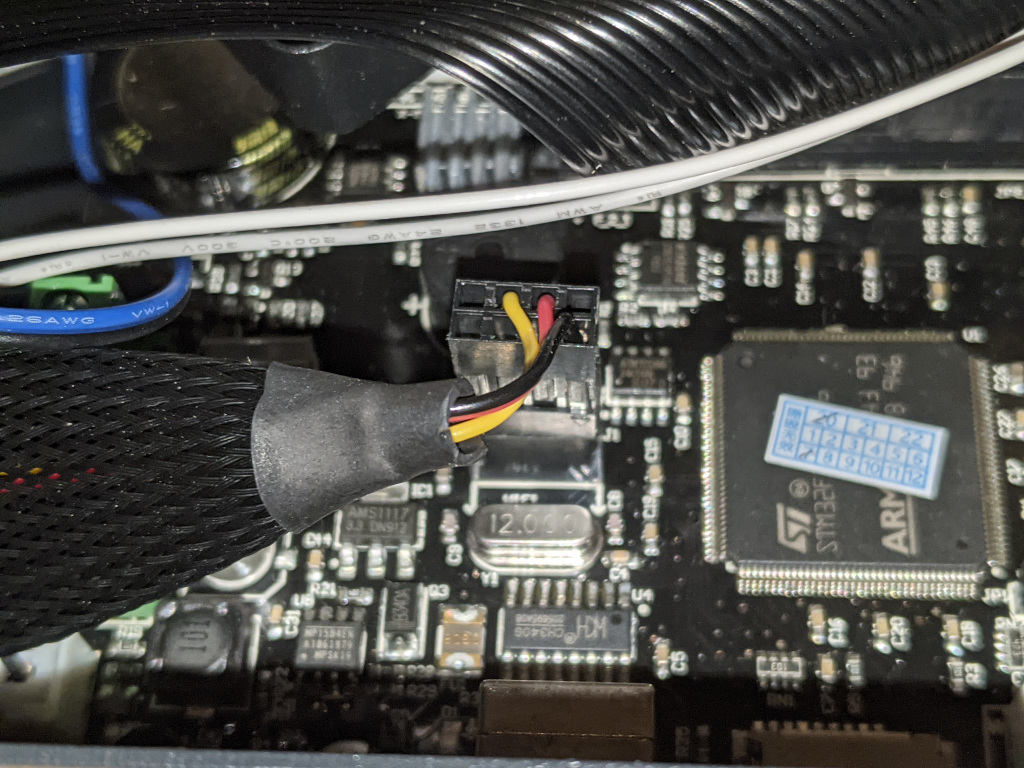
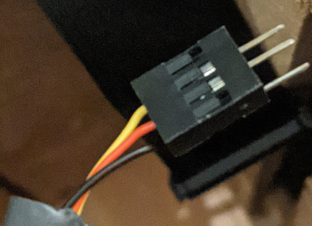
For our Level sensor I made an adapter from the original connector to Dupont so I could use the same cable type for the BL Touch. 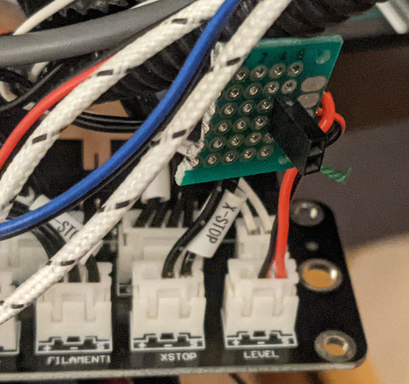
Use a multimeter to test your cables and let’s get back to changing our firmware - again!
#define BLTOUCH" // enable BLTOUCH
#define SERVO0_PIN PD12 // define servo pin as mentioned in the pinout

#define Z_MIN_ENDSTOP_INVERTING false
#define Z_MIN_PROBE_ENDSTOP_INVERTING false

//#define FIX_MOUNTED_PROBE    // disable FIX_MOUNTED_PROBE as soon as BLTOUCH is enabled
Further changes in Configurartion_adv.h:
#define BLTOUCH_SET_5V_MODECompile again, flash the firmware and test bltouch
M280 P0 S10 ; pushes the pin down
M280 P0 S90 ; pulls the pin up
M280 P0 S120 ;Self test –keeps going until you do pin up/down or release alarm
M280 P0 S160 ; Release alarm
If that works try Z-Homing but be prepared to shutdown the printer in case the Z-Axis doesn’t stop.
(optional) Replace the build plate
Now that we no longer need to ensure we have a metallic build plate for the sensor to work, we can switch to glas or epoxy. My experience with both is very good, but I stayed with FR-4. There are a lot of shops offering FR-4 in the form of a build plate.
Slicer Config
Instead of Cura I prefer using Prusa-Slicer as the support for dual extruder is better IMHO (if cura has support at all).
I uploaded my config bundle in git too, maybe makes someones life easier.
In addition I’ll share the start and stop code here, so you don’t have to find the part in the config file:
Start Code
M104 S[first_layer_temperature_[current_extruder]]; set extruder temp
M109 S[first_layer_temperature_[current_extruder]]; wait for extruder temp
M201 X1000 Y1000
G28 ; Home
M420 S1;
G0 X105 Y10 Z 0.4 F 3000 ; wait position
G92 E0 ; reset extruder
G1 E10 F240; Pee on bed
G92 E0 ; reset extruder
G0 X125 Y20 Z0.3 F2400 ; move to right
G0 X125 Y30 Z0.2  F240 ; move to inner and start printing"
Stop Code
M104 S0 ;extruder heater off
M140 S0 ;heated bed heater off (if you have it)
G91 ;relative positioning
G1 E-1 F300  ;retract the filament a bit before lifting the nozzle
 to release some of the pressure
G1 Z+0.5 E-5 X-20 Y-20 F9000 ;move Z up a bit and retract filament even more
G28 X0 Y0 ;move X/Y to min endstops
 so the head is out of the way
M84 ;steppers off
G90 ;absolute positioning
In any case, we want to tell our slicers that the printer has two extruders but has only one nozzle. In Prusa the settings is called “Single Extruder Multi Material”
I’m still working on the settings to have nice material switch during print and will update this post, as soon as I figured it out.
Wrapping up
After doing all this work, the result is pretty great. The printer is working fine. The print quality is great and the manufacturer did a great job! As the only downside - the firmware - is now fixed too, I think this printer at this price point is one of the best in market. With a little tuning of course.
If you are not tech savvy and this is your firs project with 3D printers it can easily be overwhelming there is a lot to learn, so take your time and read and use your favourite search engine extensively. Every info is out there, you only need to find it.
sources
- My Marlin Firmware Fork for Tronxy X5SA-2E
- additional 3D Parts for Tronxy X5S
- Prusa Slicer Config for Tronxy X5SA-2E with Marlin
- drucktips
- rhapsodyv on github
- thingiverse discussion
- bl touch wiring
- bl touch pin out
- bl touch on SKR 1.4
- github board pinouts
- schematics
- control signal board
- bl touch power consumption